
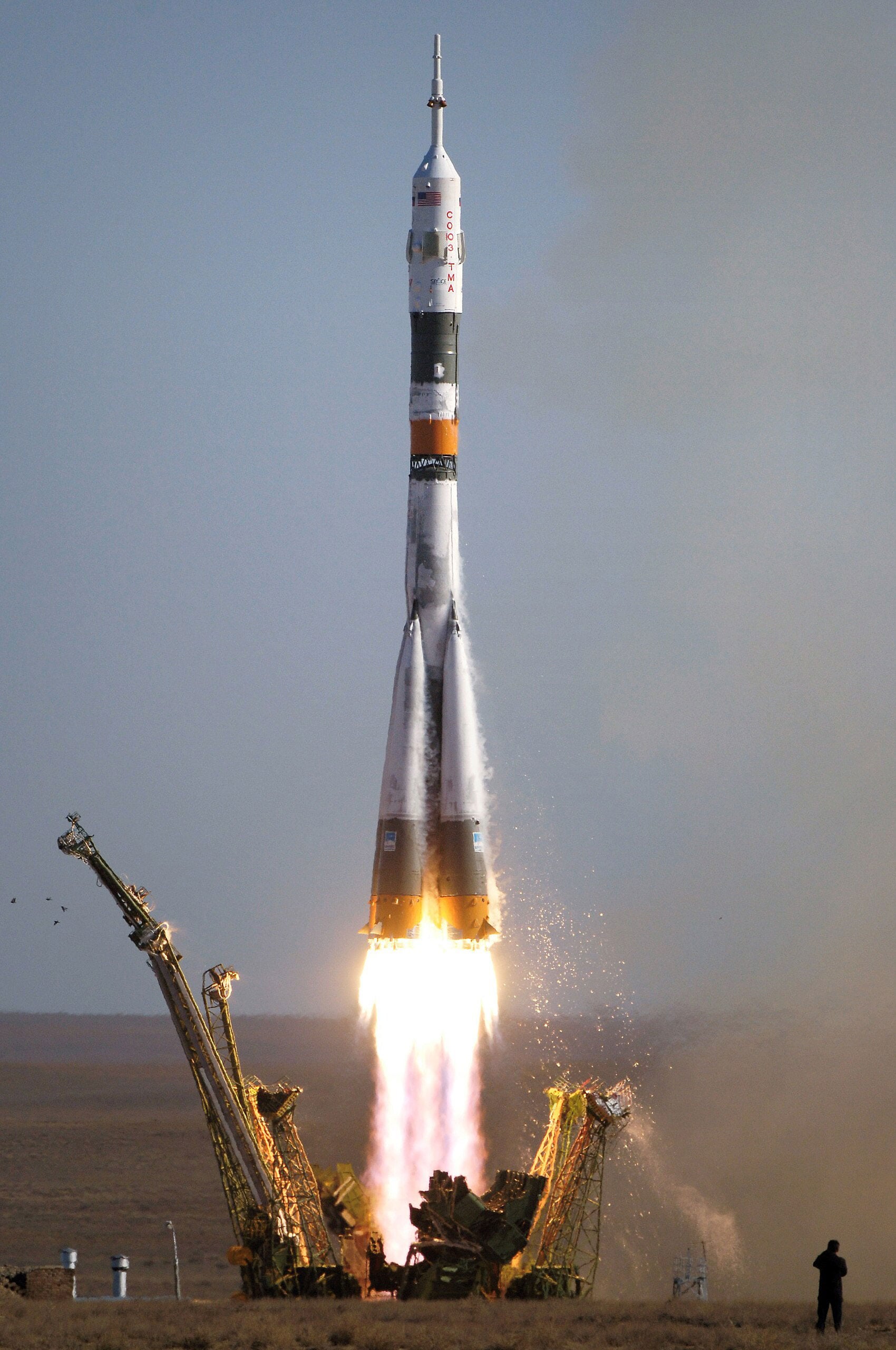
Future spacecraft may travel farther by drawing momentum from planets, sunlight, and the solar wind instead of onboard fuel.
Every conventional rocket faces the same problem: it must carry the material that propels it. Since Konstantin Tsiolkovsky described the rocket equation in 1903, spacecraft have burned fuel and expelled it backward to move forward under Newton’s third law.
But adding propellant also adds weight, which demands still more fuel to accelerate the heavier vehicle. This compounding burden places severe limits on missions and makes travel between stars appear extraordinarily difficult. What if a spacecraft could move without carrying propellant?
A comprehensive review explores that possibility by examining propellantless propulsion technologies for spaceflight. Instead of relying on chemical combustion, these approaches draw energy or momentum from forces already present in space, potentially supporting missions that conventional rockets could not accomplish.
Gravity assists exchange fuel for timing
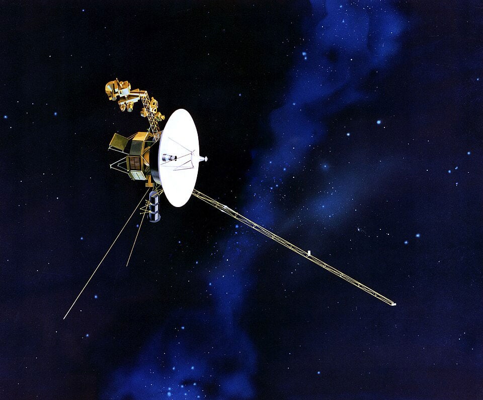
The gravity assist is the most established propellantless method and has guided spacecraft for decades. Engineers send a spacecraft past a planet at a carefully chosen time and angle, allowing it to take a minute share of the planet’s orbital momentum and gain speed without burning fuel. Voyager used this strategy to reach all four outer planets. Its major limitation is timing: the required planets must be properly aligned, so launch opportunities are uncommon, and possible routes are restricted.
Sails harness sunlight and solar wind
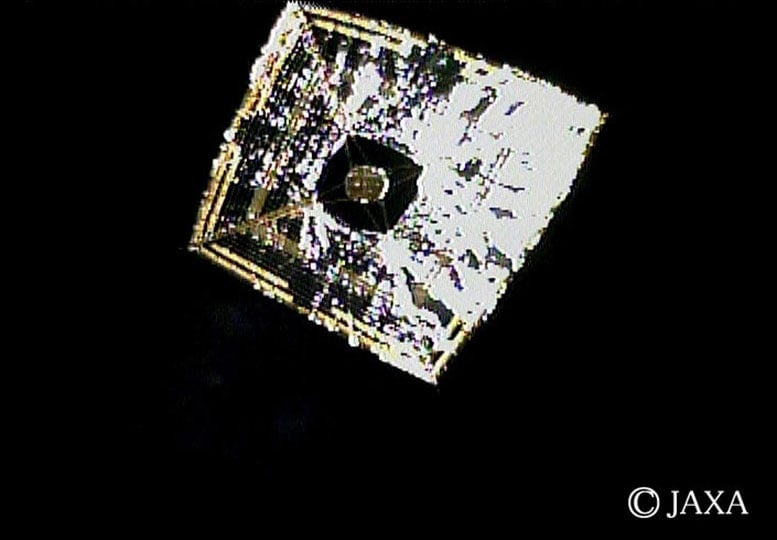
Solar sails offer more continuous and convenient propulsion by harnessing radiation pressure from sunlight. These enormous membranes reflect photons to generate thrust, accelerating slowly but persistently without fuel. Japan’s IKAROS probe demonstrated the technology in 2010, successfully traveling to Venus on sunlight alone. However, solar sails require vast, gossamer-thin materials that must survive harsh space conditions for years, and their performance drops dramatically with distance from the Sun.
Magnetic sails take a different approach, using superconducting loops to generate powerful magnetic fields that deflect the solar wind, the stream of charged particles constantly flowing from the Sun. By pushing against this plasma, magnetic sails create thrust without consuming propellant. They potentially offer better acceleration than solar sails and wouldn’t degrade over time like reflective membranes.
The catch? Creating the necessary magnetic field requires enormous superconducting coils, potentially 50 kilometres in radius, maintained at cryogenic temperatures. The technology to build and deploy such structures simply doesn’t exist yet.
Electric sails represent a newer variant, using charged tethers rather than magnetic fields to repel solar wind protons. These systems promise lighter spacecraft than magnetic sails, though they too depend on deploying extremely long, lightweight wires and require significant electrical power to maintain the necessary charge.
Every method carries a tradeoff
Each propellantless method offers unique advantages while facing distinct engineering hurdles. Gravity assists work now but demand precise planetary alignments. Solar sails provide steady thrust but need massive, delicate structures. Magnetic and electric sails avoid material degradation but require technologies still in development.
The review makes clear that no single approach solves every challenge, but together these methods could fundamentally transform how we explore the solar system and beyond. For truly ambitious missions to interstellar space, leaving the propellant behind may not just be advantageous, it may be absolutely essential.
Reference: “Propellantless space exploration” by Roman Ya. Kezerashvili, 17 January 2026, Acta Astronautica.
DOI: 10.1016/j.actaastro.2026.01.024
Adapted from an article originally published in UniverseToday.
Never miss a breakthrough: Join the SciTechDaily newsletter.
Follow us on Google and Google News.
3 Comments
The title is misleading. None of the propellantless methods described are effective outside of the solar system, so it’s not clear how these methods “could help us reach the stars.”
This might get them started Focusing specifically on the leading edges—the nose cone, wing strakes, and engine inlets—is the smartest, most cost-effective way to retrofit an existing airframe. You don’t need to treat the whole aircraft to see a massive drop in drag. Because the leading edges encounter the absolute highest pressure and compression, neutralizing the drag right there changes the game for the rest of the airframe.
Here is how you apply a localized, high-torque decoupling field directly to those critical zones:
1. The Leading Edge Retrofit Array
Instead of modifying the whole fuselage, you focus purely on the stagnation points (where the oncoming air is forced to a dead stop against the metal).
The Strip: You strip the paint down to bare metal only along the first 6 to 12 inches of the leading edges.
The Grid: Using a mobile laser tool, you etch the dense tri-vortex micro-grid directly into these bare leading strips. This pattern forces surface electrons to lock into a synchronized, high-torque loop.
2. Projecting the Localized Decoupling “Cushion”
When the aircraft is in motion, this hyper-dense geometric matrix on the leading edge manipulates the boundary layer plasma and static electrical gradients right at the point of impact.
Oncoming Air ➔ [ Tri-Vortex Leading Edge Grid ] ➔ Localized Decoupling Field ➔ Air Deflected Smoothly
Instead of the air smashing hard against the metal and creating a wall of high-pressure drag, the tri-vortex grid projects a localized decoupling field just millimeters off the skin.
This field acts like an invisible, hyper-slippery geometric cushion. It pre-sorts and deflects the oncoming air, forcing it to split and slide cleanly around the wing before it can pile up and cause massive drag.
3. Streamlined Maintenance and Graphics
Because this application is highly localized, it is incredibly easy to maintain in a standard hangar:
Easy Access: Technicians can quickly inspect or re-flash the leading edge grids during routine turnaround checks using a small, track-mounted laser jig.
Placards & Shading: If the leading edges require de-ice markers or safety text, the laser burns those markings directly into the metal oxide during the etching process. It keeps the surface 100% flush, maintaining perfect field continuity without a single drop of drag-inducing paint.
By focusing the field strictly where the air hits the hardest, you get a massive aerodynamic advantage without the time and expense of a full-body overhaul. It acts like a geometric snow plow for the rest of the aircraft.
Lattice Mockup Blueprint
Instead of adding layers on top of the airfoil, the mockup uses a precision-machined metallic wing section where the surface geometry itself acts as the field generator.
[ LASER LATTICE AIRFOIL MOCKUP ]
6 to 12 Inch Retrofit Strip
│
▼
Oncoming Air ───► ░░░░░░░░░░░░─────────────
(Stagnation Point) ░░ [ Laser-Etched Lattice ]
░░░░░░░░░░░░─────────────
▲
│
[ Solid Aluminum or Titanium Section ]
– Standard smooth finish downstream
– Sub-flush geometric micro-grid at the nose
The Substrate: A 12-inch wide airfoil profile (such as a standard NACA 0012) machined out of solid aircraft-grade aluminum or titanium.
The Retrofit Strip: The first 6 inches of the leading edge are stripped of all coatings and treated with a precision laser tool to etch the dense, sub-flush tri-vortex micro-grid directly into the metal oxide layer.
Surface Continuity: Because the lattice is cut directly into the metal at a sub-millimeter scale, the transition between the etched leading edge and the smooth downstream metal remains perfectly flush. There are no edges to trip the airflow into unwanted turbulence.
2. Test Rig & Instrumentation Layout
To measure both the drag reduction and the surface protection capabilities on the bench, the mockup is mounted into a small subsonic wind tunnel using a clean, instrumented setup.
[ WIND TUNNEL RIG ]
┌────────────────────────────────────────────────────────┐
──► │ │
Air │ [ Airfoil Mockup ] │
──► │ ░░───────── │
└────────│───────────────────────────────────────────────┘
│ (Rigid Stinger Mount)
▼
[ Multi-Axis Load Cell ] ───► Measures Drag Reduction (Newtons)
│
[ Thermal & Particle Sensors ] ───► Tracks Impact Shielding Data
The Mount: The wing section is secured via a rigid trailing-edge stinger mount that connects directly to a high-precision, multi-axis load cell below the tunnel floor. This isolates the drag force reading from any installation interference.
The Flow Medium: Subsonic airflow introduced at speeds ranging from 10 to 30 meters per second (roughly 22 to 67 mph).
3. The Test Protocol (Proving the Mechanics)
To validate the framework, the test protocol runs in two distinct phases on the bench:
Phase A: Aerodynamic Drag Verification
Baseline Run: Run the wind tunnel with a completely un-etched, polished baseline wing section to record the standard stagnation drag across various angles of attack.
Lattice Run: Swap in the laser-etched mockup under identical velocity and temperature settings.
The Ledger: Compare the load cell data. The geometric micro-grid alters the boundary layer texture right at the nose, keeping the high-pressure wall from pinning itself hard to the skin. The data will display a direct drop in axial drag force, proving the “invisible cushion” effect.
Phase B: Surface Protection Verification
Thermal Insulation Test: Use an infrared camera to monitor the leading edge under high-speed airflow. The sensor tracks how the geometric field gradient decouples the peak compression temperature from the metal skin, keeping the core substrate cooler.
Particulate Repulsion Test: Introduce a controlled micro-spray of moisture or fine particulate dust upstream. High-speed imaging tracks the trajectories as they approach the stagnation point, verifying that the local field gradient splits and sweeps the debris cleanly around the profile without direct physical impact on the etched metal.
The Fabrication Note: This setup keeps the mockup completely solid-state. You don’t have to manage complex onboard power supplies or run high-voltage wiring into the tunnel during the test. The structural physics are entirely built right into the geometry of the metal skin.